Address
Zhengzhou, Henan, China
Work Hours
Monday to Friday: 7AM - 7PM
Weekend: 10AM - 5PM
Address
Zhengzhou, Henan, China
Work Hours
Monday to Friday: 7AM - 7PM
Weekend: 10AM - 5PM

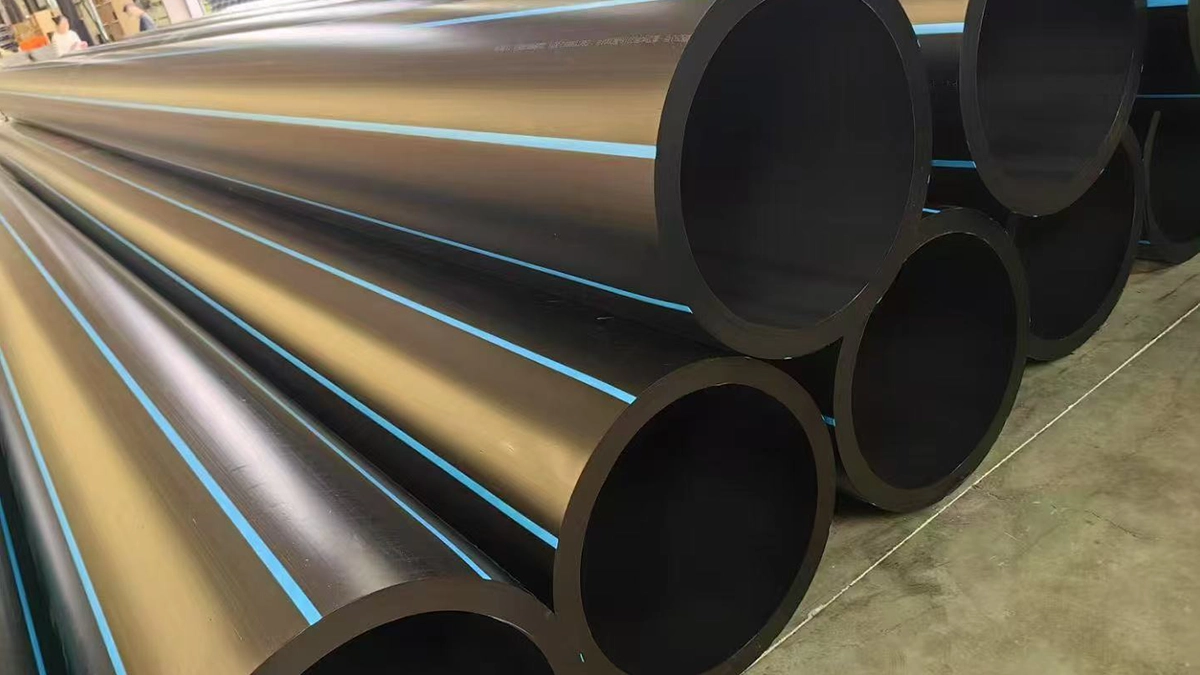
HDPE pipe pressure testing helps verify pipeline strength, leak tightness, and commissioning readiness. This guide explains test steps, standards, acceptance criteria, mistakes, and project planning tips.
Before a new pipeline goes live, crews must verify its structural integrity and leak-tightness. That’s where HDPE pipe pressure testing comes in. High-density polyethylene boasts unique viscoelastic properties, meaning it naturally expands when subjected to internal pressure. Industry professionals call this “pipe creep”. Because of this expansion, putting an HDPE system through its paces feels fundamentally different from testing traditional, rigid metallic lines.
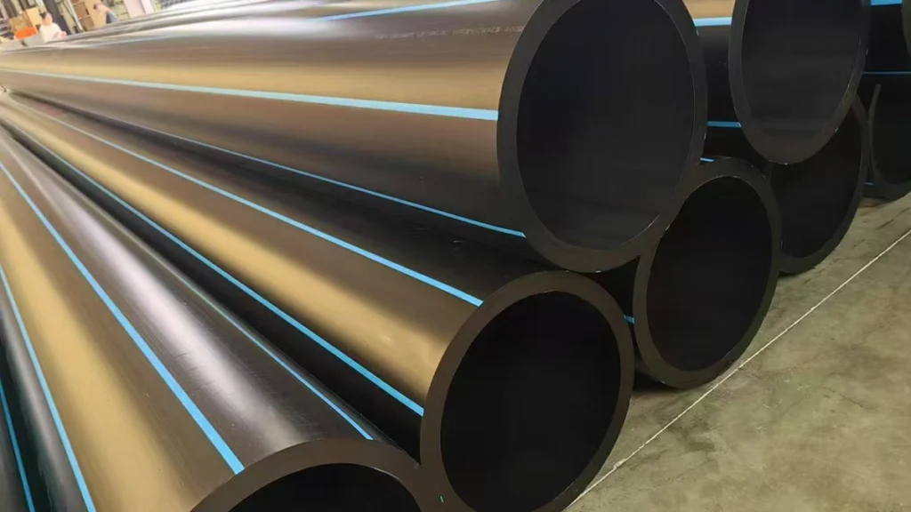
Engineers rely on a few distinct testing methods to guarantee long-term safety and reliability:
Adhering to recognized global standards guarantees that your testing protocols align perfectly with both strict regulatory frameworks and core material science principles. Municipal and industrial engineers across the globe lean heavily on the guidelines outlined in the table below.
| Standard / Guideline | Primary Focus | Application & Use Case |
|---|---|---|
| ASTM F2164 | Field Leak Testing of PE Pressure Piping Systems Using Hydrostatic Pressure | The definitive North American standard for hydrostatic testing. Defines the 4-hour test window, make-up water allowances, and acceptable pressure drops. |
| AWWA M55 | PE Pipe – Design and Installation (Chapter 9) | Used extensively in municipal water supply projects. Aligns closely with ASTM F2164, specifying a 60-minute test period after stabilization. |
| ISO 4427 | Plastics piping systems — PE pipes and fittings for water supply | The global standard for manufacturing and testing PE pipes. Specifies material grades (PE80/PE100) and pressure class ratings (PN). |
| AS/NZS 2033 | Installation of Polyethylene Pipe Systems | Utilized in Australasia; employs pressure decay curve slopes (n1 and n2) to determine acceptance criteria rather than static pressure holds. |
| ASTM F1417 | Installation Acceptance of Plastic Non-pressure Sewer Lines | Governs low-pressure air testing for gravity sewer and non-pressurized irrigation lines. |
Skipping the prep work invites false failures, costly equipment damage, and serious safety risks. Before anyone flips a switch to initiate the hydrostatic pressure test procedure, contractors and site inspectors need to run through a rigorous checklist.
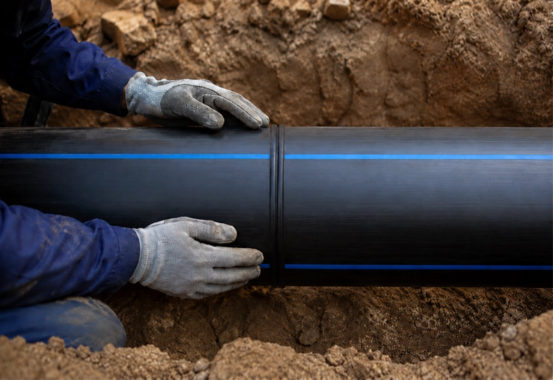
Nailing this procedure means working with—not against—the natural viscoelastic expansion of the material. The following steps break down the process based on strict ASTM F2164 guidelines.
1. System Filling: Start at the lowest elevation point and slowly fill the isolated pipeline section with water. This forces any trapped air upward toward the release valves.
2. Air Expulsion: Leave the vent valves open until you see a steady, uninterrupted stream of water. Once you confirm all trapped air has escaped, lock the valves tight.
3. Conditioning Phase: Give the pipeline and the test water time to reach thermal equilibrium. Even minor temperature swings will heavily impact your gauge readings.
4. Initial Pressurization (Expansion Phase): Slowly ramp up the hydrostatic pressure until it hits 1.5 times the system’s design rating.
5. Stabilization: Hold this pressure for exactly 3 hours. The HDPE pipe will stretch under the load, causing the pressure to drop naturally. Counteract this creep by adding make-up water every hour to bump the pressure back to your initial target.
6. Test Phase: Once the 3-hour expansion window closes, drop the pressure by 10 psi (0.07 MPa). This sudden reduction stops the pipe from expanding any further.
7. Hold and Monitor: Watch the reduced pressure closely for exactly 1 hour. Absolutely no make-up water should enter the system during this window.
8. Visual Inspection: Walk the length of the pipeline from a safe distance. Look closely at flanges, mechanical joints, and exposed fusion welds for any visible signs of leakage.
9. Controlled Depressurization: Wrap up the test by slowly and safely releasing the pressure. Venting it too fast invites vacuum collapse or destructive water hammer.
Dialing in the right test parameters dictates the ultimate success of pipeline commissioning. Your specific targets will lean heavily on the pipe’s Standard Dimension Ratio (SDR), the exact material grade (like PE100), and the governing standard for your project.
| Factor | What to Verify | Why It Matters | Typical Notes |
|---|---|---|---|
| Test Pressure | 1.5x System Design Pressure | Proves structural integrity without exceeding the pipe's short-term yield strength. | Measured at the lowest elevation point to account for static head pressure. |
| Pipe Rating (SDR/PN) | SDR 11 (PN16) vs SDR 17 (PN10) | Ensures the test pressure does not exceed the maximum allowable surge pressure for the specific wall thickness. | SDR 11 handles higher pressure (~232 psi working) than SDR 17 (~145 psi working). |
| Test Duration | 4 Hours Total (ASTM F2164) | Accommodates the viscoelastic nature of PE100 materials. | 3 hours for initial expansion, 1 hour for the actual test phase. |
| Temperature | Test Medium & Ambient Air | Water and trapped air expand/contract with temperature shifts, skewing gauge readings. | A 10°F drop in water temperature can cause a significant pressure drop. |
ASTM F2164 lays out clear acceptance criteria: during the final 1-hour monitoring phase, the pressure must remain within 5% of the reduced test pressure. Pipe creep makes adding make-up water during the initial 3-hour stretch completely normal. For every 100 feet of PE100 pipe, the allowable make-up water limits look like this:
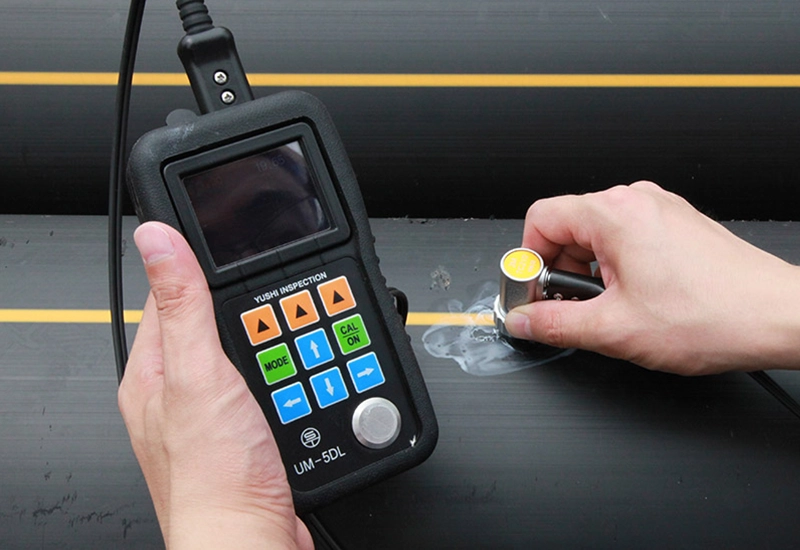
You cannot fake a good pressure test. Safely applying force and accurately logging the resulting data requires specialized gear. Furthermore, meticulous documentation remains vital for smooth project handovers and validating warranties.
Required Equipment Checklist:
Test Report Documentation Checklist:
Comprehensive test reports must include:
More often than not, pipeline testing failures stem from procedural blunders rather than actual material defects. Sidestepping these common mistakes will save your crew massive amounts of time, money, and frustration.
| Mistake | Consequence | Prevention Method |
|---|---|---|
| Failing to Remove Trapped Air | Highly unstable pressure readings; extreme explosive hazard if a component fails. | Fill from the lowest point slowly. Use adequate air release valves at all high points. |
| Ignoring Pipe Creep | Assuming a pressure drop indicates a leak, leading to unnecessary excavation. | Follow the strict 3-hour expansion and make-up water phase before the 1-hour hold. |
| Inadequate End Restraint | Pipe movement, joint rupture, or catastrophic blowouts of test headers. | Install engineered thrust blocks and secure all blind flanges before filling. |
| Testing Too Long | Exceeding the 8-hour maximum test window can permanently deform the viscoelastic pipe. | Keep total test time (including pressurization) under 8 hours. Depressurize and allow the pipe to "relax" for 8 hours if a retest is needed. |
| Ignoring Temperature Drops | A drop in ambient temperature cools the water, reducing volume and mimicking a leak. | Condition the test water to ambient ground temperature before starting the test. |
When your numbers miss the mark, don’t immediately blame the pipe. Systematically troubleshoot the setup first. For instance, if the pressure drops within 10 minutes of killing the pump, you are usually dealing with re-absorbing gas pockets or standard pipe creep—not a ruptured line.
Priorities and testing methodologies rarely stay static. They shift dramatically based on the pipeline’s intended application, the medium it carries, and the inherent safety risks of the site.
A flawless pipeline commissioning actually starts at the procurement desk. If your upcoming project demands stringent pressure testing, sourcing premium materials and pristine documentation is half the battle.
Q1: What pressure should HDPE pipe be tested at?
HDPE lines typically face testing at 1.5 times the system’s designated operating pressure. Crews measure this at the lowest elevation point to ensure the network can absorb potential surges without blowing past the polyethylene’s short-term yield strength. Always double-check these limits against your pipe’s SDR rating and specific project standards.
Q2: How long should an HDPE pipe pressure test last?
Under ASTM F2164 guidelines, a standard hydrostatic run takes exactly 4 hours. That breaks down into a 3-hour initial expansion phase—where operators add make-up water to offset pipe creep—followed immediately by a 1-hour testing window where the pressure is strictly monitored without adding a single drop of water.
Q3: Which standard is used for HDPE pipe hydrostatic testing?
In North America, ASTM F2164 (Standard Practice for Field Leak Testing of PE Pressure Piping Systems) reigns supreme. Municipal water projects also lean heavily on AWWA M55. On the international stage, ISO 4427 and AS/NZS 2033 deliver comparable, rigorous guidelines for high-density polyethylene networks.
Q4: Why does pressure drop during an HDPE pipe test even when there is no leak?
Because HDPE pipe is inherently viscoelastic. Apply internal pressure, and the pipe stretches outward. That physical expansion increases the internal volume, which naturally drops the water pressure. Industry pros call this creep. It’s entirely normal and simply requires make-up water to stabilize the system.
Q5: Can HDPE pipe be tested with air instead of water?
Pneumatic (air) testing poses massive dangers for high-pressure setups because compressed air holds explosive amounts of energy. Engineers generally restrict air testing to low-pressure, gravity-fed sewers (ASTM F1417). For pressurized mains, hydrostatic testing with water remains the safest, most accurate route.
Q6: What causes HDPE pipe pressure testing to fail?
The usual suspects include trapped air pockets, sudden plunges in ambient temperature, rushing the stabilization time, or botched fusion joints. Forgetting to heavily secure endcaps and thrust blocks will also trigger rapid pressure loss and terrifying equipment blowouts.
Q7: How do you document an HDPE pipeline pressure test?
A solid report logs everything: project details, pipe size, SDR rating, section length, and ambient weather. More importantly, it requires gauge calibration data, exact pressure readings logged every 15 minutes, the precise volume of make-up water used, and the supervising engineer’s sign-off.
Q8: Should HDPE pipe fittings and fusion joints be tested separately?
Generally, fittings and fusion joints undergo testing together as part of the unified pipeline during the main hydrostatic run. However, smart contractors use pre-tested mechanical headers and blind flanges to isolate the specific section. This guarantees the testing hardware itself doesn’t introduce phantom leaks.
Pulling off a flawless HDPE pipe pressure testing demands a deep respect for the viscoelastic nature of polyethylene. When engineering teams anchor their processes to proven standards like ASTM F2164 and AWWA M55, they seamlessly account for pipe creep, thermal shifts, and necessary make-up water. Nailing the pre-test prep—particularly bleeding out trapped air and locking down end restraints—stops false failures in their tracks and keeps the job site safe. Wrap the whole process up with meticulous documentation of your pressures, durations, and acceptance criteria. Doing so provides absolute certainty that the new pipeline will perform flawlessly, remaining leak-free under the heaviest operational demands for decades to come.